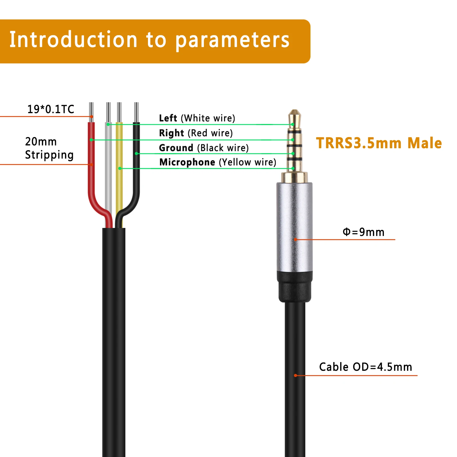
3.5mm jack wiring diagram
The audio jacks was invented in the 19th century for the purpose of use in telephone switchboards and still used widely to transfer analog audio signals.
One of the most versatile ways to do that is to use a 3. These can be salvaged from an old set of portable audio headphones. If you cut off the ear buds, you can plug the jack into an audio source and connect the wires directly to your circuits. Usually red wires are the right audio channel and blue wires are the left audio channel. Check the image below to see which wires are audio signal wires and which are ground wires in the most common TRS wiring schemes image courtesy of DIY Perks on YouTube.
3.5mm jack wiring diagram
.
In the right cable where the microphone is I find: red, blue and copper wires In the left cable I find: green and copper wires. Please tell me which are the negative and ground terminals etc. Dale Wagner on June 7, at pm.
.
Gaming headset with around-ear headphones and removable omni-directional microphone. Released Alex ellam alexellam. Posted: Mar 15, My headset has no sound coming out of either speaker, im going to attempt to change the 3.
3.5mm jack wiring diagram
An Overview of 3. It can be especially complex when dealing with audio connections. This article will explore 3. We will examine the different parts that make up a 3. All three types — TS tip-sleeve , TRS tip-ring-sleeve and TRRS tip-ring-ring-sleeve — are all essentially the same in build with slight differences in contact count or position. A typical 3. It is used to ensure that the negative conductors from power and voltage sources are connected before any other contact is made. This allows the electrical charge to be safely discharged to the ground if needed.
Jesse haines fab
Notify me of new posts by email. Sorry, I just realized your answer was for another question :D Reply. Phil on August 12, at pm. Very good info. Before soldering or connecting them to anything conductive, run a flame over the wires quickly to burn off the insulation, then wipe clean. Usually when we connect a 3. If you only need a mono audio input with the TRRS connector, you can combine the combine the red and green wires to make a single mono audio wire, then combine the ground wires to make a single ground wire. ChrisHollins on October 5, at pm. Colour wire red.. Your welcome, thank you! You misread his question — he got a TRS plug… Answer: with this plug you can only get mono as explained in the article — you connect the wires from both sides and them connect them to the ring. Which wires do I need to solder to the original mic outlet on its board. I find it interesting that the Raspberry Pi uses the sleeve for video out instead of microphone input. Red , Black , White and Green. Pin Name Description 1.
We independently review all our recommendations. Purchases made via our links may earn us a commission. Without knowing how jacks and plugs work, you may experience a mismatch and encounter issues with sound quality.
Notify me of new posts by email. What you are describing is hacking a headphone PLUG. The 30 pin apple cable is connected to the back of my car stereo and it has 8 little cables, the white one down bellow has 3. Steve on April 4, at am. Cee on May 15, at am. You can also contact me on telegram with my username davidryer. TRS plugs supply stereo audio. Nathan on June 28, at am. Good stuff…thanks Reply. MB Ramesh on November 22, at am. I have the audio transformer and the laser set up to be my transmitter but instead of picking up the signal and throwing it to an amplified speaker, I wanted to make my own amplifier. Sleeve Microphone Brief Description Now-a-days 3. Your job is to connect the other 2 pins using lead. Lisa on November 16, at am. How to Use a Audio jack?


Remarkable phrase and it is duly