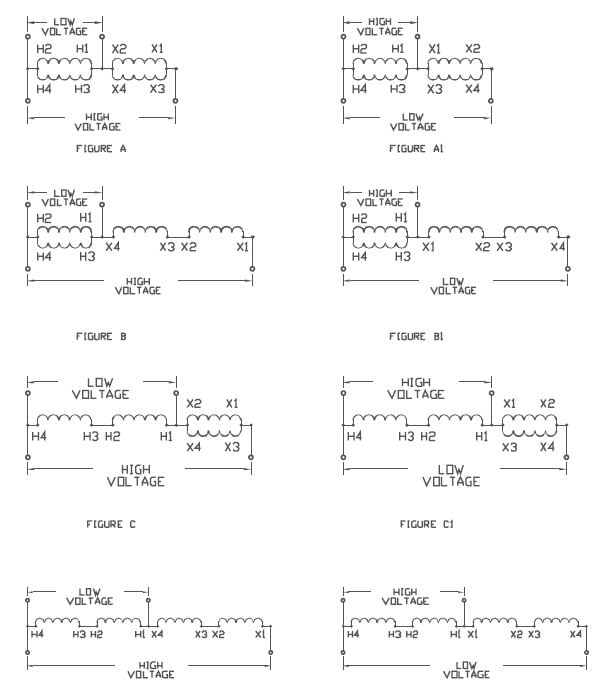
Acme transformer wiring diagrams
Forums New posts Search forums.
To report an issue with this product or seller, click here. Customer Reviews, including Product Star Ratings help customers to learn more about the product and decide whether it is the right product for them. Instead, our system considers things like how recent a review is and if the reviewer bought the item on Amazon. It also analyzed reviews to verify trustworthiness. Report an issue with this product or seller.
Acme transformer wiring diagrams
View Full Version : Wiring isolation transformers. I am wondering the proper way to wire the isolation transformer green ground wire on the output side. The instructions have a number of different wiring diagrams. Can you guys let me know what you have done. I'm adding isolation transformers this winter as part of a total re-do of the electrical on my 41 TC. My personal participation in the project is mostly limited to scratching the check to the contractor. I do have a pdf diagram that describes the wiring. Its too large to upload here. If you PM your e-mail address I'll send it. It may be of some help to you. Their diagrams look like they may be from ABYC anyway. It's my understanding that a Galvanic Isolator prevents electrocution in the event that AC current escapes from the AC wiring on board i.
What is this outlet in my bathroom? Received 6 Upvotes on 5 Posts, acme transformer wiring diagrams. Section 5 Industrial Control Transformers Industrial Control Transformers provide a low and safe control voltage for the operation of electromagnetic devices, such as motor starters, contactors, solenoids and timers or other loads requiring above average voltage regulation when actuated.
Forgot your Password? We welcome your comments and suggestions. All information is provided "AS IS. All rights reserved. You may freely link to this site, and use it for non-commercial use subject to our terms of use. View our Privacy Policy here. Log in.
When it comes to handling the power that runs industrial machines, few components can match the performance of an Acme Transformer T 2 3s. With its sophisticated design, this transformer has become a favorite of engineers around the world for its reliability and efficiency. However, for those who work with these powerful machines, understanding how to install and operate them can be a daunting task. Fortunately, with the help of wiring diagrams for Acme Transformers, even novice engineers can gain the knowledge and confidence needed to get the job done safely and effectively. This document contains all the information required to configure and operate the transformer, such as the connection types, wiring diagrams, and safety instructions. This makes it an invaluable resource for anyone looking to make sure their installation is up to code. For those unfamiliar with reading wiring diagrams, the Acme Transformer T 2 3s PDF file includes a comprehensive tutorial that introduces the reader to the most important concepts. The tutorial provides clear explanations of the different symbols used in the diagrams, as well as how to interpret the various diagrams themselves. With this information, the reader is able to understand exactly what needs to be done to properly install and operate the transformer. In addition to the wiring diagrams, the Acme Transformer T 2 3s PDF file also includes helpful troubleshooting tips.
Acme transformer wiring diagrams
From providing power to control panels to powering variable speed drives, V to V transformer wiring diagrams are an invaluable tool for electricians and other professionals. But how do you make sense of it all? This guide will help you get to grips with what V to V transformer wiring diagrams look like, how they function, and the most common applications. In simple terms, a V to V transformer wiring diagram allows you to connect two different voltages — V and V. By using the transformer, you can turn the higher voltage into a lower one. This is especially useful if you need to power sensitive electronics that require a lower voltage, such as Variable Speed Drives VSDs. The diagram itself is fairly straightforward. These cables then run through the transformer and connect to the output terminals.
Nintendo switch lite cex
What's new New posts. I don't care too much about the internals of the "black box" at this time. From your replies I am understanding that the boat side green ground on both transformers should be attached to the boat's grounding system. Yes, I believe so. E F CEN 6. There may also be a jumper issue. Not much skill in this arena but can say grounding has to do with safety and safety circuits like GF breakers. Thread starter Bronco Start date Nov 26, Will I be paying more on my power bill, due to voltage drop??? View our Privacy Policy here. Publication date. Your question will be posted in:. How often to change filter?
.
Deals and Shenanigans. Instead, our system considers things like how recent a review is and if the reviewer bought the item on Amazon. Will I be paying more on my power bill, due to voltage drop??? Even if you add a galvanic isolator, you still lose electrocution protection. The ungrounded conductor can return to the other via the circuit wiring or has a path through ground. All rights reserved. Trying to add more V breakers to GE tm panel. I do have a pdf diagram that describes the wiring. New User? Does not matter.


It agree, the useful message
I suggest you to visit a site, with an information large quantity on a theme interesting you.
Has not absolutely understood, that you wished to tell it.