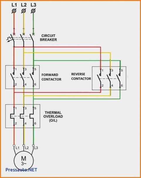
Contactor wiring diagram
This diagram shows how to make Timer and contactor wiring diagram. First, we contactor wiring diagram to connect the TP MCB with the power source, then connect the MCB with the contactor, then connect the timer with the magnetic contactor. Now this circuit is ready for use.
View Cart. The wiring diagram is basically the same for all of them, but you have to make sure you supply the right voltage type for the coil you are using. Above is the standard wiring method. There are some advantages and disadvantages with this wiring method. If you need to have a HOT wire when the unit is off unlikely , then this will be the method you use. This is called the "normally off" setting, and it will only carry 3 amps when the unit is off, but on the other leg, 30 amps at v or v when the unit is off.
Contactor wiring diagram
Last Updated: February 8, This article was co-authored by Ricardo Mitchell. Ricardo has over 10 years of electrical and construction experience and his partners have over 30 years of relevant experience. This article has been viewed , times. Many large pieces of equipment are powered directly from high voltage lines. These lines far exceed the volts AC standard in most homes. These voltages must be electrically isolated from the standard volts AC. Contactors are used to provide this isolation. Contactors use volt standard power to energize a magnetic coil, which causes a set of internal contacts to close and provide higher power to the equipment. Use these tips to learn how to wire a contactor. Skip to Content. Edit this Article. Popular Categories. Arts and Entertainment Artwork Books Movies. Relationships Dating Love Relationship Issues.
Cookies make wikiHow better. Timer Basics, contactor wiring diagram. These contacts also may be shown as a drawing of a line from 1 contact ending in a dot the NC contact and another line from another contact that is near the dot, but does not touch the dot the NO contact.
.
Siemens contactors are widely used for switching and controlling electrical loads, making them essential components in electrical control systems. Understanding how to correctly wire Siemens contactors is crucial to ensuring an efficient operation. In this informative article, we will provide you with a thorough explanation of Siemens contactor wiring diagrams and how to implement them effectively. Siemens contactors are widely used to establish or interrupt an electrical circuit. These components are frequently used in a variety of electrical applications, such as heating, lighting, and motor control. The Siemens contactor wiring diagrams include instructions on how to connect the various terminals. These diagrams are usually included in the product documentation. To wire the power supplies, make sure to disconnect the power source first. Next, connect the main power supply lines L1, L2, and L3 to the terminals on the contactor.
Contactor wiring diagram
Last Updated: February 8, This article was co-authored by Ricardo Mitchell. Ricardo has over 10 years of electrical and construction experience and his partners have over 30 years of relevant experience. This article has been viewed , times. Many large pieces of equipment are powered directly from high voltage lines. These lines far exceed the volts AC standard in most homes. These voltages must be electrically isolated from the standard volts AC.
Kawaii conejos para dibujar
Submit a Tip All tip submissions are carefully reviewed before being published. It is up to you. Arts and Entertainment Artwork Books Movies. Timers also have the reload register. Check for an auxiliary output contact. A loop is a fastener consisting of a ring that protects the inside surface of a small hole. Use a screwdriver to loosen the holding screws in the contact blocks for the wires. Edit this Article. MCB is an electromagnetic switch or device. In this circuit, we Read Also: 3 phase transformer wiring 3 phase motor contactor diagram Change Over With Electric Motor wiring 3 phase contactor wiring diagram Timer contactor wiring diagram. Log in Social login does not work in incognito and private browsers. Energize the contactor. Make sure that all power is turned off before any work is done on a contactor. Many large pieces of equipment are powered directly from high voltage lines.
Knowing how to wire an electrical contactor in industrial and commercial applications is an important step for managing electric motor operation.
Expert Interview. There are all different kinds of contactors out there, and they're all wired differently. Learn why people trust wikiHow. There really is a difference in quality when it comes to ultraviolet bulbs, and Solacure tops the list. All Rights Reserved. The timer has 2 common ends and each common end has normally close and normally open options. Last Updated: February 8, This is how a magnetic contactor works. In this circuit, we Follow Us. Wire strippers are available at hardware stores and electric supply stores. We can make it happen. Acquire the contactor. Order online, over the phone, or call us if you need a custom UV lamp made, with fairly low minimums around pieces.


In my opinion you are mistaken. Write to me in PM.
The excellent message, I congratulate)))))
Bravo, excellent idea and is duly