Cummins top stop injector adjustment
Log in.
Log in. Sign up. Home Forums Farming Community Tractors. JavaScript is disabled. For a better experience, please enable JavaScript in your browser before proceeding. Can you use either one?
Cummins top stop injector adjustment
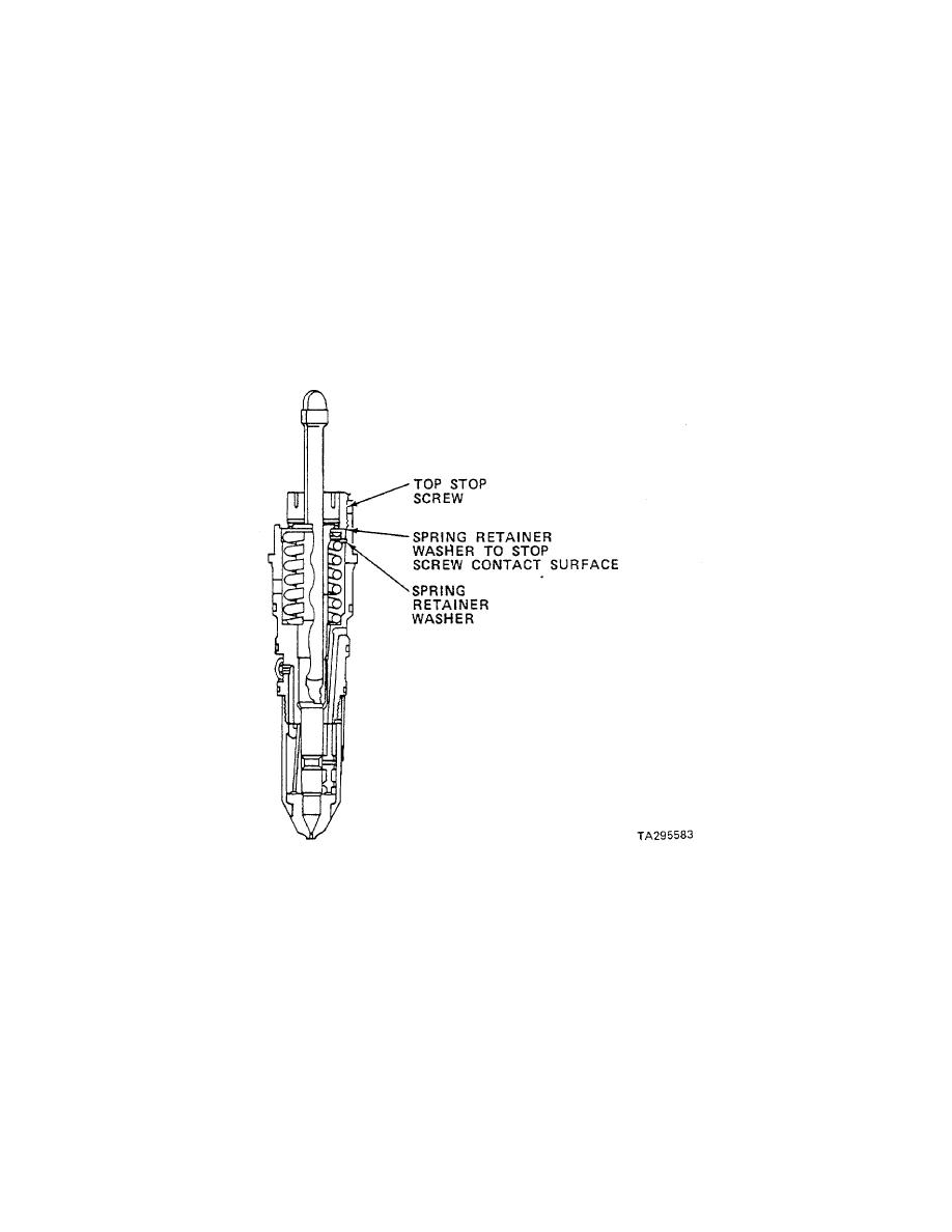
We'll discuss the theory and procedures for setting injector plunger travel using the dial indicator method D. Included is the recommended procedure for checking and adjusting crossheads. We'll discuss the effects of crosshead adjustment related to valve operation. This is a Top Stop adjustment fixture It's required to set Top Stop plunger travel, and to torque the splined locknut to 55 ft. The plunger travel is set by preloading the injector spring with the weighted handle at a prescribed travel. Plunger travel for Top Stop injectors cannot be set in the engine. Always use the adjustment fixture to set Top Stop injector plunger travel. Travel is changed by turning the adjusting nut. The upward travel stops when the sprin-g washer contacts the nut. The downward travel stop is the injector cup.
Another guy was pulling the Pan down and Found a 12" long punch in the Pan sump!
Steel Soldiers now has a few new forums, read more about it at: New Munitions Forums! Sure, ad-blocking software does a great job at blocking ads, but it also blocks useful features of our website like our supporting vendors. Their ads help keep Steel Soldiers going. Please consider disabling your ad blockers for the site. Forums Bookmarks New posts Search forums.
Follow along with the video below to see how to install our site as a web app on your home screen. Note: This feature may not be available in some browsers. Forums New posts. What's new New posts Latest activity. Log in Register.
Cummins top stop injector adjustment
Log in. Sign up. JavaScript is disabled. For a better experience, please enable JavaScript in your browser before proceeding. Sort by Oldest first Oldest first Newest first Most reactions. Your manual will no doubt show you this, but one dial registers via a long stem through a removed injector hole the piston position relative to crankshaft rotation, while another registers the push rod travel. Different thicknesses of rocker box gaskets are available to move the low mounted rocker rollers in or out of contact with the cam lobe. One gasket choice has to provide a satisfactory average for two cylinders. If you disturb an old engine to change these, you must pull the housing end plugs to renew the "O" rings.
Dragon age stroud
Carousel Previous. The numbers represent the cylinders to be adjusted when the pointer is aligned with one of the "VS" marks. JavaScript is disabled. For a better experience, please enable JavaScript in your browser before proceeding. The torque adjustment point is located on the outer-base-circle of the injector lobe at after-top-center during the power stroke. If you want to see a real turbo set up, talk to your local old timmer at Cummins about the Hyper-Bar KV I found a set of feeler gauges lodged in the valve train, not the reason for low power, but disappointing to find inside an engine. When the accessory drive is positioned at the "A" mark, cylinders 1 and 6 have traveled on their downward stroke. When necessary, retorque them to maintain tolerances. Slowly release the rocker lever. Now insert the feeler gauge between the rocker lever and the crosshead contact surface.
Package Dimensions: W7. The typical timeframe for a core to be approved is between weeks after the part is received. To avoid this delay, please select to pay the refundable core charge and we will ship your product according to our shipping policy Same day shipping if ordered by 2pm EST.
I found a set of feeler gauges lodged in the valve train, not the reason for low power, but disappointing to find inside an engine. The next step was the NT xt. You should upgrade or use an alternative browser. Please add support steelsoldiers. When removing the gauge, you should still feel a slight drag. I've Disabled AdBlock. If you find unacceptable wear conditions on the adjusting components, replace them. The injector type designates the method of overhead adjustment. Now you are ready to set a in. The injector roller has just passed B. I-2 V-6 A At this position both the jntake and exhaust valves are closed, providihg lash in the valve train to ensu re correct clearance settings. We are working to resolve this issue. Just need to be able to extend the end of the dial indicator so it can reach the top of the plunger right above the spring. The roller is positioned on the inner base circle of the injector lobe.


Not logically