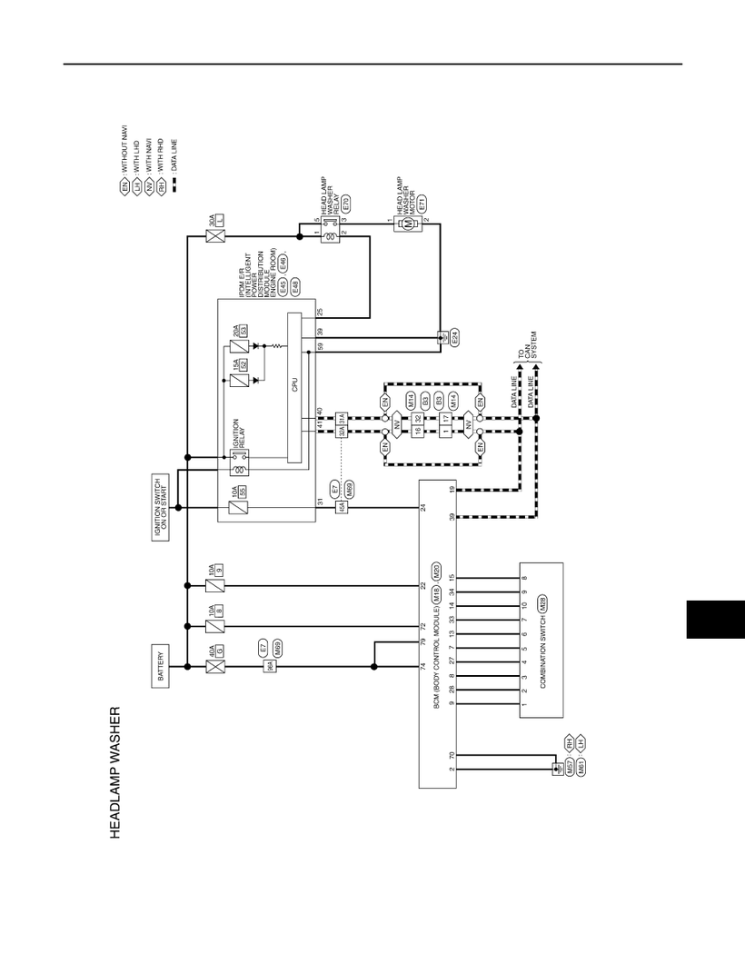
Nissan tiida wiring diagram
Search your problem.
P ECM Check DTC. Perform the following procedure if DTC is displayed. Symptom Table is useful. Refer to EC, "Symptom Table". Check related service bulletins for information.
Nissan tiida wiring diagram
Log in. Sign up. Home Forums Nissan Versa Versa. JavaScript is disabled. For a better experience, please enable JavaScript in your browser before proceeding. I have manually opened the hatch and removed the trim. The switch test OK. The switch connects to the wiring harness via small two pin brown connector. One pin with a blue wire has 12V on it. The other pin with a light brown wire has 9V on it. Should be GND 0V. If I disconnect the switch at this connector and short the 12V pin to ground, the mechanism operates. I traced the light brown wire to a connector behind the plastic at the bottom of the door pillar near the drivers right foot This is a right hand drive car. Then it changes to a yellow wire.
This page shows the wiring from the BCM through the switch on the hatch that unlocks the rear hatch and then through the front door lock. Perform the following procedure if DTC is displayed, nissan tiida wiring diagram. Carousel Next.
.
By using this website, you automatically accept that we use cookies. What for? Toggle navigation. Home Workshop Manuals Nissan Tiida. Nissan Tiida The Nissan Tiida is a small automobile produced by the Japanese manufacturer Nissan since , spanning two generations. For the first generation of Tiida manufactured between and , the series is designated C11 and was sold as a five-door hatchback and four-door sedan. The engine range included 1. Sales in China commenced in June It is available only as a five-door hatchback, and is notably not sold in Japan.
Nissan tiida wiring diagram
The Nissan Tiida is a mid-size sedan produced by the Japanese car manufacturer Nissan from to It is a popular vehicle due to its versatility and affordability. To keep up with this popularity, many owners need to be able to access their vehicle's wiring diagrams. These diagrams provide quick access to the information needed to diagnose and repair electrical problems with the Tiida. Nissan Tiida wiring diagrams are essential for any owner or technician who needs to repair or troubleshoot an electrical issue on the vehicle. They provide detailed diagrams showing how the different parts of the car's electrical system are connected and how they interact. This makes it possible to pinpoint the source of any problem quickly and accurately.
Nirmal lottery nr 210
Sort by Oldest first Oldest first Newest first Most reactions. The ECM receives the voltage signal and detects the fluctuation of the engine revolution. Block port B. Check ground connections E15, Check resistance between engine coolant temperature sensor terminals by heating with hot water as shown in the figure. Remove fuel level sensor unit. Do not depress accelerator pedal even slightly. It will take at least 35 seconds. The weight should be less than 1. Perform component function check. Crankshaft position sensor 3. Refer to EC- , "Description". Refer to EC, "Component Inspection". GO TO 3. Crank engine while depressing accelerator pedal.
Please view this preview to check your job is included.
Disconnect heated oxygen sensor 2 HO2S2 harness connector. Check vacuum gauge indication before 60 seconds passed after starting engine. EVAP control system pressure sensor 2. The ECM adjusts the injection pulse width according to the sensor voltage signal. Check ignition timing with a timing light. SEFK E. The ability to seal C the vent is necessary for the on board diagnosis of other evaporative emission control system components. There is no priority for 1st trip freeze frame data. I dismantled the door and the yellow wire does not go in. Diagnostic only picks up p engine code but still no fix?


What excellent words
This theme is simply matchless :), it is pleasant to me)))