Ph diagram 134a
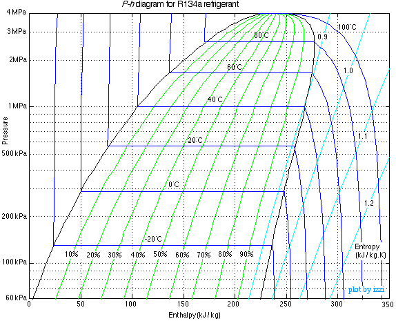
On the P-H diagram, pressure is indicated ph diagram 134a the y-axis and enthalpy is indicated on the x-axis. The upside down U figure shown on the diagram designates the points at which the refrigerant changes phase. The left vertical curve indicates the saturated liquid curve and the right vertical curve indicates the saturated vapor curve.
Ra Pressure Enthalpy Chart. Scroll down to find download buttons for pressure enthalpy charts in either Metric or Imperial Units. Downloads as a PDF. You can download that software free of charge also using this link. Save my name, email, and website in this browser for the next time I comment. The Engineering Mindset.
Ph diagram 134a
.
The cid cookie helps to identify unique visitors and understand their site behaviour at different times.
.
If you read my previous post about sealed system basics , you know that understanding the thermodynamic states of refrigerants saturated, subcooled, and superheated is essential to sealed system troubleshooting. In that post, I explained these states in terms of a simple pressure-temperature table. While that keeps things simple, it doesn't really give you a strong visual and mental model for how the refrigeration cycle works thermodynamically. That's why we're going to spend this whole post learning how to read a P-H diagram. It takes a bit more work than just reading a P-T table, but this diagram is where those values on the P-T table come from , so learning to read it will give you a deeper understanding of what's going on in the sealed system. Pretty overwhelming, right? I remember how quickly my eyes started crossing when I first looked at one of these. This diagram conveys a ton of information, but some of it isn't really necessary for us techs, and the stuff that is useful gets lost in the jumble if you don't know what to look for. Let's strip this diagram down to something really simple, then start adding lines back in step by step.
Ph diagram 134a
K Sat. I have enjoyed your youtube channel very much, thanks. I wander if you had any plans to publish the RA thermodynamic property tables? I was looking to run through the same calculations and compare the theoretical COP and cooling loads etc with the real experimental data. Thank you because of your complete description For full description I have a qaustion ,why do you start with kpa Pressure in step one of ra refrigeration? Save my name, email, and website in this browser for the next time I comment. The Engineering Mindset.
16 pounds to php
HVAC Pressure enthalpy chart. The refrigerant entering the evaporator is a cold, partial liquid-vapor mixture. This cookie is installed by Google Universal Analytics to restrain request rate and thus limit the collection of data on high traffic sites. This cookie, set by Tribal Fusion, collects data on user visits to the website, such as what pages have been accessed. Quantserve sets the mc cookie to anonymously track user behaviour on the website. Others others. In an ideal condenser, no sub-cooling occurs. NID 6 months NID cookie, set by Google, is used for advertising purposes; to limit the number of times the user sees an ad, to mute unwanted ads, and to measure the effectiveness of ads. One of the most important skills needed for the professional engineer in the HVAC and Refrigeration field is navigating the refrigeration cycle on a pressure-enthalpy diagram. Functional cookies help to perform certain functionalities like sharing the content of the website on social media platforms, collect feedbacks, and other third-party features.
The pressure-enthalpy diagram is the most common graphical tool for analysis and calculation of the heat and work transfer and performance of a refrigeration cycle. The change in pressure can be clearly illustrated on the p-h diagram.
The cookie is a session cookies and is deleted when all the browser windows are closed. Necessary Necessary. Close Privacy Overview This website uses cookies to improve your experience while you navigate through the website. Figure 8 is a simplified P-H diagram illustrating the constant temperature lines. Understanding the P-H Diagram On the P-H diagram, pressure is indicated on the y-axis and enthalpy is indicated on the x-axis. Support more content. This cookie is used to track the specific store view or the locale selected by the shopper. This cookie is set by the provider McAfee for website security. The mix region is the phase change region, where any addition of enthalpy will cause additional liquid to vaporize instead of raising the temperature. Electric Heating Mar 7, You'll like these too!


I am sorry, that has interfered... This situation is familiar To me. Let's discuss. Write here or in PM.
I recommend to you to visit a site, with a large quantity of articles on a theme interesting you.
What necessary words... super, remarkable idea