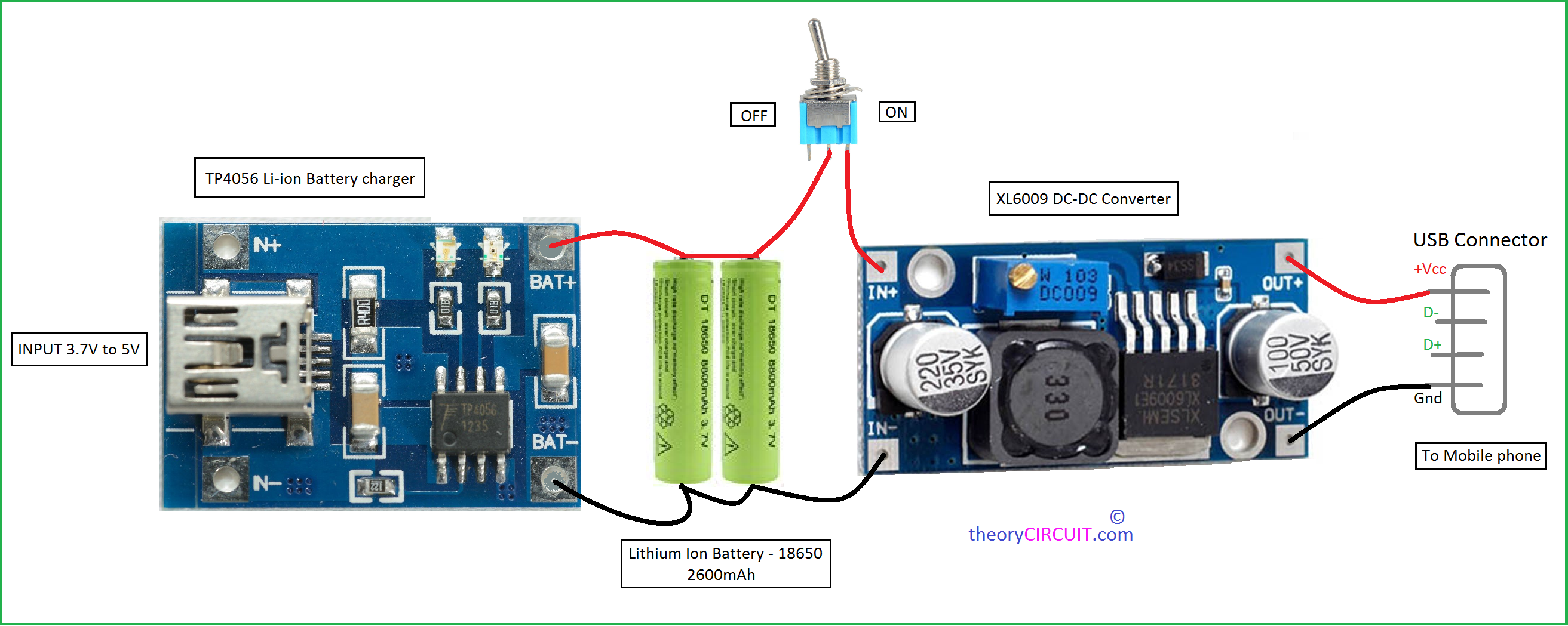
Power bank schematic circuit diagram
The features of the digital products are growing enormously which triggers the frequent usage of smart phones in several applications.
The circuit of the power bank has two building blocks — 1 Battery recharge circuit and 2 Output amplifier circuit. If the output voltage required would have been 3. But, the required output voltage is 5V, that is why amplifier circuit at the output of the device is a must. As per the circuit sections, the device also operates in two stages — 1 Charging of the battery and 2 Taking the output from the battery through amplifier circuit. The IC needs minimum 4V to 8V voltage for its operation. It can provide maximum mA charging current to the battery and a fixed 4. The circuit as given in the datasheet of the IC is used to design the charger.
Power bank schematic circuit diagram
D- 1 GND 1. Open navigation menu. Close suggestions Search Search. User Settings. Skip carousel. Carousel Previous. Carousel Next. What is Scribd? Academic Documents.
The part list will be the same as mentioned in the previous paragraph except the inductor, which will now have a turn ratio using a 27SWG wire or any other suitable size magnet wire. Your email address power bank schematic circuit diagram not be published. If you think that the above IC based power bank charger circuit looks cumbersome and an overkill, you could probably try a Joule thief concept for achieving quite the same results, as shown below:.
However, there are some products that you can make in your home with little things that you would get from the market. One such product is the power bank circuit. The power bank circuit composition is straightforward and can be made with little effort. There are numerous uses of the power bank circuit; for instance, you can use it as a spare power bank if you need it. There are numerous ways to make the power bank circuit; e. However, another easy way to make the power bank circuit is by using different modules that can be used to charge the cell phone. This project is revolving around the making of the charging circuit from scratch.
Through our unrivalled customer-centric approach, we partner with leading companies in numerous markets to deliver solutions for their most complex challenges. Power banks are a great power source when out of your house. This convenient and portable power source can charge your phones several times. While this magical device has so many usages, if you are a manufacturer of a power bank circuit board or want to build your own power bank, this article is meant for you. This article deals with an insight into power bank circuit board or power bank PCB, that act as one of the core parts of a power bank. A power bank printed circuit board is a piece of silicon chip, that acts as a mainboard of the power bank. When assembled, a power bank PCBA has power input and output points, capacitors, diodes, etc.
Power bank schematic circuit diagram
This power bank can be used for charging smartphones. This power bank circuit uses two integrated modules and a lithium-ion battery. The first module is a lithium-ion battery charger and the second is a DC-DC boost converter module. Circuit diagram of the power bank is shown in Fig.
Marks and sparks
Semiconductor Data Book: Characteristics of approx. AI-enhanced title. The power bank designed in this project can be used to charge any electronic device which needs a regulated 5V and 4A maximum current for its operation. He has more than 15 years of experience in practical electronics. Maybe I mistakenly remove a tiny resistor or component during soldering. Carousel Next. It also has an LED indication to indicate the presence of supply from battery source. Message to Emma. You may also like: What battery chemistries are used in electric vehicles? Assuming the battery voltage to be 7. High-Performance Digital Storage Oscilloscopes. More other project kits, visit kitsNspares.
This article will take you through all the aspects of a power bank circuit at home, with an in-depth steps to building power bank along with different modules, circuit board, connection diagram, and external case to use with it. The best way is to carry a mobile charging source i.
Tell Us What You Think!! The output voltage can be adjusted to 12V by changing a resistor in module but the maximum current will be mA. A4 Plans A4 Plans. Picpgm Usb v1. Hareendran is an electronics hobbyist, freelance technical writer and circuit designer. Notify me via e-mail if anyone answers my comment. Srry im new with electronics and i dontwhich should i buy, Thanks. How can one get the complete circuit of this power bank. What is the way out to achieve this sir while carrying repairing sir. This power bank can be used for charging smartphones. One such product is the power bank circuit.


This topic is simply matchless :), it is pleasant to me.
Speak to the point