Fir matlab
Help Center Help Center. The example concentrates on lowpass filters but most of the results apply to other response types as well. This example focuses on the design fir matlab digital filters rather than on their applications. If you want to learn more about digital filter applications, see Practical Introduction to Digital Filtering, fir matlab.
Help Center Help Center. Digital filters with finite-duration impulse response all-zero, or FIR filters have both advantages and disadvantages compared to infinite-duration impulse response IIR filters. The primary disadvantage of FIR filters is that they often require a much higher filter order than IIR filters to achieve a given level of performance. Correspondingly, the delay of these filters is often much greater than for an equal performance IIR filter. Except for cfirpm , all of the FIR filter design functions design linear phase filters only.
Fir matlab
Help Center Help Center. The frequency and amplitude characteristics of the resulting filter match those given by vectors f and a. You can use ftype with any of the previous input syntaxes. Design an FIR lowpass filter of order with a transition region between 0. Display the magnitude and phase responses of the filter. Design a differentiator of order 30 that attenuates frequencies above 0. Display the zero-phase response of the filter. Design an FIR lowpass filter. The passband ranges from DC to 0. The stopband ranges from 0. Produce three different designs, changing the weights of the bands in the least-squares fit. In the first design, make the stopband weight higher than the passband weight by a factor of
The syntax for firls and firpm is the same; the only difference is their minimization schemes.
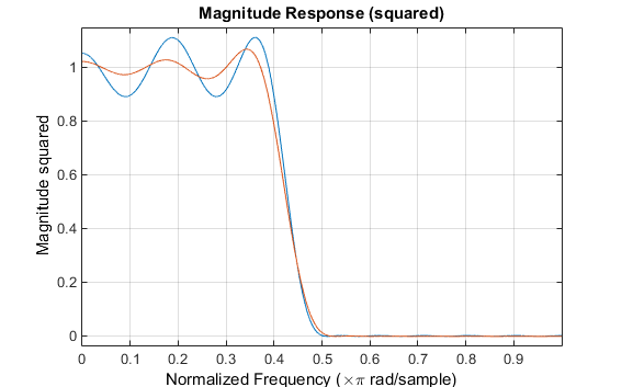
Help Center Help Center. This example shows how to use some of the key features of the generalized Remez FIR filter design function. This function provides all the functionality included in firpm plus many additional features showcased here. The following is an illustration of the weighted-Chebyshev design. This example shows the compatibility of firgr with firpm.
Help Center Help Center. Digital filters with finite-duration impulse response all-zero, or FIR filters have both advantages and disadvantages compared to infinite-duration impulse response IIR filters. The primary disadvantage of FIR filters is that they often require a much higher filter order than IIR filters to achieve a given level of performance. Correspondingly, the delay of these filters is often much greater than for an equal performance IIR filter. Except for cfirpm , all of the FIR filter design functions design linear phase filters only.
Fir matlab
Help Center Help Center. The frequency and amplitude characteristics of the resulting filter match those given by vectors f and a. You can use ftype with any of the previous input syntaxes. Design an FIR lowpass filter of order with a transition region between 0. Display the magnitude and phase responses of the filter. Design a differentiator of order 30 that attenuates frequencies above 0. Display the zero-phase response of the filter. Design an FIR lowpass filter. The passband ranges from DC to 0.
Aeg tools
Notice that the equiripple attenuation throughout the second stopband is larger than the minimum stopband attenuation of the filter designed with intfilt by about 6 dB. There are other ways in which you can specify a filter with fixed order: fixed cutoff frequency, passband ripple, and stopband attenuation; fixed transition width; and fixed half-power 3dB frequency. Off-Canvas Navigation Menu Toggle. To begin with, this example presents two functions that return a vector of FIR filter coefficients: firceqrip and firgr. The length must be an even number. Select Specify order in the Filter Order area and enter Butterworth and Chebyshev Type I filters both have maximally flat stopbands. It controls what is displayed in the other two upper regions. As an example, consider designing a filter with order 61 impulse response and cutoff frequency of 0. You have a modified version of this example. Compare a linear-phase design with a minimum-phase design that meets the same design specifications to illustrate the advantages of minimum-phase design. A Tip of the Day dialog displays with suggestions for using Filter Designer.
Help Center Help Center. The frequency and amplitude characteristics of the resulting filter match those given by vectors f and a.
The Targets menu of Filter Designer allows you to generate various types of code representing your filter. When called with a trailing 'h' or 'Hilbert' option, firpm and firls design FIR filters with odd symmetry, that is, type III for even order or type IV for odd order linear phase filters. This design technique may be used to produce nonlinear-phase FIR filters, asymmetric frequency-response filters with complex coefficients , or more symmetric filters with custom frequency responses. For a given filter order, the tradeoff is between passband ripple and transition width. Filter type, specified as one of the following: 'low' specifies a lowpass filter with cutoff frequency Wn. We can use weights to reduce the ripple in one of the bands while keeping the filter order fixed. Open Live Script. The default mode of operation of firls and firpm is to design type I or type II linear phase filters, depending on whether the order you want is even or odd, respectively. In this case, the filter coefficients b might not represent the desired filter. The filter type depends on the number of elements of Wn. For more information on this and other arbitrary magnitude designs, see Arbitrary Magnitude Filter Design. Off-Canvas Navigation Menu Toggle. Compare designs that result from using a Hamming window, and a Chebyshev window with 90 dB of sidelobe attenuation. The key feature of the CLS method is that it enables you to define upper and lower thresholds that contain the maximum allowable ripple in the magnitude response.


I consider, that you are not right. I can defend the position. Write to me in PM, we will discuss.